Nominal load at COG: 42t – Centre of gravity: 1200mm – Standard tyres: L 4x2 – Transmission type: W – Max. Reach horizontal: 6.315…
Nominal load at COG: 42t – Centre of gravity: 1200mm – Standard tyres: L 4x2 – Transmission type: W – Max. Reach horizontal: 6.315m – Weight: 65.5t
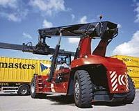
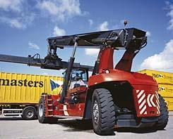
Reach stacker DRF 420-60 S5 manufactured by Kalmar, production years [(year-year)].
Explore detailed DRF 420-60 S5 container handler specs: technical details, table charts and data sheets to download. Check also the other container forklift models produced by Kalmar.
More technical details, like: wheel base, dimension lxwxh, displacement, revolutions at max torque, max. torque, no. of cylinders, cylinder bore x stroke, emission level are available in the full technical specs.
L = pneumatic tyres, x = drive, SE = superelastic, P = PUR (Elastollan, Vulkollan), V = solid rubber, ND = low pressure tyres, 3 = three-wheel, 4 = four-wheel, 6 = six-wheel All specifications, prices and weight refer to basic models incl. spreader
The brake circuit is separated from the hydraulic system and has its own tank, cooler and high-pressure filter. A temperature transmitter in the separate tank regulates the cooler fan. The foot-brake valve, which controls the oil feed to the brakes, is sensitive enough so that the driver can brake optimally yet still gently. The parking brake is activated automatically when the ignition is turned off.
Transmission
The transmission transfers power from the engine to the hydraulic pumps and drive line. The engine and gearbox control systems work together to find the optimum balance between power and fuel economy at any given point. The transmission system consists of a torque converter and a gearbox. The same gearbox is used whichever engine is chosen. The gearbox is automatic, but can partly be shifted manually. The torque converter is a hydraulic coupling positioned between the engine and gearbox. The gearbox and torque converter work together via a joint hydraulic system.
Drive line
The propeller shaft and drive axle transfer the power from the transmission to the driving wheels. The mountings on the propeller shaft are fitted with cross-flanges for optimum strength. The drive axle shifts gear down in two stages, differential and hub reduction. The engine only achieves maximum torque at the drive wheels, which spares the transmission.
Engine
A Volvo engine is standard. Cummins is available as optional extra. The engine provides power for driving and the working hydraulics. The engines are low-emission turbo diesels with unit injectors and intercoolers. The design of the combustion vessels, along with the precise fuel injection control, ensures more efficient combustion. Emissions decrease, while power and torque increase. The engines fulfill the requirements of 97/68*2004/26 EC stage 3, US EPA Tier 3. The engine and transmission cooler is a single unit that uses the same fan. The engine cooler’s separate expansion vessels are fitted with a level transmitter that indicates low coolant level. When the engine temperature is too high or the coolant level or oil pressure too low, the engine’s power output is actively reduced. Should the oil pressure fall below a certain level, the fuel feed to the engine is cut off automatically.
Temperature Control
In order to maintain optimum functionality in the hydraulic system even under extreme operating conditions, cleaning and cooling of the hydraulic oil is highly efficient. The brake circuit is separated from the rest of the hydraulic system and is fitted with its own cleaning process and cooling system.
Handling
Attachment
The primary function of the attachment is to firmly attach the container during lifting. This is done with four twistlocks which rotate, thereby securely gripping the container’s corner fittings. The mechanical levelling ensures that the twistlocks reach the corners, even if the container is leaning. The attachment can easily be adapted to different container standards. A hydraulic motor drives the function via chains. The container can also be moved sideways to facilitate loading and unloading, or to compensate for unbalanced loads. Two hydraulic cylinders perform the side-shift movement.
Attachment and rotator hydraulics
The functions are fed with a constant pressure, which means there is no pumping of hydraulic oil when the functions are not in use. One valve serves all the hydraulic functions in the attachment. The valve ensures that each hydraulic function is fed the exact amount of oil needed to optimise the speed of the functions’ movements. The attachment functions are damped in the end positions.
Increased capacity
In some cases, high capacity requirements in the second and third rows of containers, or on the far rail track, call for the benefit of support legs. In other cases, it may be the restricted handling space that determines the most suitable model.
Hydraulic components and couplings
The number of hydraulic components and hydraulic couplings has been minimised. The main valve has an integrated servo, which helps increase control of the oil flow and keep the number of components to a minimum. The boom’s lifting and extension cylinders are fitted with double gaskets. Moreover, the machine is fitted with extremely reliable, well-sealed ORFS (O-Ring Face Seal) couplings in all the hydraulic hoses as standard.
Service accessibility
The top covers on the frame can be removed quickly and easily. Most of the main components are easily accessible from above in the broad frame when inspection and maintenance need to be carried out. The cabin can also be moved lengthwise thus further increasing ease of access.
Driveliness
Steering system
The steering axle has been cut from a single piece of robust steel, which means as few maintenance-requiring parts as possible and high structural strength. The hydraulics that feed oil to the steering cylinder are optimized for enhanced driving sensation. Orbitrol and the priority valve jointly provide gentle yet precise steering movements.
Equipment
Ergonomics
Controls and instruments are intuitively positioned and work the way a driver would expect. Search lights in the buttons and switches make them easy to identify and use, even in darkness. In the centre above the steering wheel is a display showing operating information, warning messages, error codes etc. To the left of the display is the panel for warning and indication lamps. The driver’s seat and control lever for the lifting functions can be adjusted to the optimum individual driving position. The pedals are designed for high comfort, with a hanging accelerator. The internal dimensions are otherwise generous, offering an open floor space.
The distributed and redundant control system
For the reachstacker to work perfectly a robust communication network is needed, along with a system that gives the functions power. Two things are needed for a command initiated by the driver to result in a particular function, or for several functions to work together: power-feed and communication. The power-feed supplies the machine’s electrical and electrohydraulic functions with voltage, while the communication system controls and checks that the functions have been activated, waits in standby mode or indicates a fault.
Control functions
The driver and machine communicate via the Kalmar Information Terminal (KIT) and the Kalmar Information Display (KID). Control signals initiated by the driver are transferred to the KCU, which handles all incoming signals from the controls in the cabin, and sends messages out into the communication network. The system also distributes information to the driver such as alarm warnings, operating details and action-guided information. In these cases, messages are sent from one of the nodes in the network, captured by the KCU, and then presented in the KID or the panel for warning and indication lamps. The KID shows information from the control units in the form of messages, status, fault indication etc.
Redundant communication network
A network of distributed control units (nodes) using limited cabling and fewer couplings, meaning fewer sources of error. The power-feed for each node is independent of the other nodes, which help prevent other nodes from being disrupted, should one stop working. The same applies to the transfer of control signals. Both the power-feed and control signal transfer are redundant, so that power or signals always have two paths to choose for maintaining communication, thus offering extra safety and reliability.
Safety
Sound and vibration
The cabin is separately suspended and isolated from the frame with powerful rubber dampers. Effective shock absorption minimises vibration. The cabin is fitted with insulation material both inside and out. The maximum noise level inside the cabin is 72 dB (A) measured according to DIN4535.
Buy & Rent
Used Kalmar Reach stacker for sale
LECTURA gathers best information from many sources about Reach stacker. See first rate deals on the most popular classified websites showing second hand Reach stacker available in many countries.
Get in touch for more details:
Compare Kalmar DRF 420-60 S5 with similar Reach stacker
Whether you need to get value of your Kalmar DRF 420-60 S5 or valuation of your Reach stacker fleet, LECTURA Valuation will help. Simply fill the machine details and see the pricing information for Reach stacker in few clicks.
Get spare parts for Kalmar DRF 420-60 S5 easily from our partners
Do your lookup for high quality parts for Kalmar DRF 420-60 S5 online!
With a few, easy steps, you will find generic and genuine parts and replacements in well-catalogued lists. Wether you are dealer or an owner, LECTURA can lead you to the right direction.
Check the best offers from our partners and order the Reach stacker spare parts easily today - worldwide.
In case you look into transport options for your machine, take advantage of our services. Query the ideal transport quotes for Reach stacker created on dimensions and weight. Our partners provide major services to meet your requirements.
Yale Lift Truck Technologies announces the ERC2.2-3.5VG2, a 2,200- to 3,500 kg capacity electric cushion tyre lift truck designed for high-intensity warehousing applications.
.jpg)
.jpg)
.jpg)

.jpg)
.jpg)
.jpg)

.jpg)