NPK now offers hammer grease specially formulated to meet severe job requirements. The grease is available in three different temperature ranges - 350°, 500°, and 2000°. All are compatible with Autolube systems. Universal Plus and Super Duty are lithium soap based products that resist washout and contain NPK-10 additive for surface protection in friction affected areas. Chisel Paste is an aluminum complex soap base with 12% graphite and copper additives for extreme operating conditions.
Autolube grease line pre-filling
It is mandatory that the supply line from the Autolube main pump to the connection on the hammer is primed with grease before it is used. Failure to do this will result in no grease being administered to the hammer tool for two to three hours. This can and will result in severe galling of the tool and tool bushing.
Do not slant hammer
For the most efficient demolition, align the direction of force from the boom with the penetration direction of the tool. Failure to do this decreases the transfer of energy from the piston to the rock and increases the bending forces at the fulcrum of the tool. This unnecessary added stress leads to the following problems: Premature bushing wear and/or tool breakage. Breakage of tie rods. Breakage of bracket bolts. Decrease in transfer of energy translates to reduced production. When the tool binds from incorrect working angle, the sound of the hammer changes.
Hammer operation
Keep the boom direction of force in the same direction the tool is penetrating. Use the boom cylinder to preload the hammer (apply downforce), and use the bucket and stick cylinders for alignment. Keep the tool tangent to the arc of the boom.
Hammer Fastener Torque
If hammer or hammer bracket fasteners are found to be loose, use the following charts. Medium strength thread adhesive should be used on all the valve assembly bolts and the gas charge valve. All other bolts should be lubed with anti-seize compound.
Operating cycle
Hammer lines
Typically, the pressure line is arranged on the left side of the boom and the return line on the right side. Flow to the hammer is controlled from an auxiliary valve on the carrier or from an NPK supplied valve. Hydraulic oil is routed back to the tank through the carrier’s oil cooler and filter.
Hammer control valve
NPK uses two general types of control systems, depending upon the carrier model:CONTROL SYSTEM USING CARRIER AUXILIARY OR SPARE VALVE SECTION. This type of installation utilizes an existing carrier valve. Any additional parts, such as a mechanical linkage, hydraulic pilot control valve, flow control valves, etc., are furnished in the NPK HYDRAULIC INSTALLATION KIT. Special hydraulic pressure control valves are not required. The NPK HYDRAULIC HAMMER operating pressure is self-regulating.CONTROL SYSTEM USING THE NPK MULTIVALVE. For carriers not equipped with a suitable auxiliary or spare valve section, the NPK HYDRAULIC INSTALLATION KIT includes a solenoid operated, priority flow control valve to operate the NPK HYDRAULIC HAMMER. The NPK MULTIVALVE is specifically designed for the operation of boom mounted attachments.
Changing the filter element and hydraulic oil
Change the filter element and hydraulic oil at the intervals described in the operation manual of the excavator when using a hydraulic implement. Another method is to set up an oil sampling schedule and change accordingly.
Preferred Method
The preferred method to measure or charge the nitrogen gas pressure is with the hydraulic system temperature stabilized at maximum operating temperature. The chart showing values for “Operating Temperature” should be used, see below.
Alternate Method
The nitrogen gas pressure can be measured or charged at ambient temperature (cold), before operating the hammer. See the chart “Ambient Temperature” below.
Gas Charging Kit
All NPK hydraulic hammers are furnished with the following gas charging kit. In addition, a nitrogen tank and pressure regulator valve (not furnished with the hammer) are required. These can be obtained from your local welding supply house. A regulator valve is available from NPK.
Gas Charge Checking the Gas Pressure
Turn the T-handle (g2) clockwise. As the T-handle is screwed in, a resistance is encountered. By turning the T-handle further, the nitrogen gas pressure will be indicated on the pressure gauge (g8). Stop turning the T-handle when the gauge reads pressure. Do not over tighten! Compare the gauge pressure with the NITROGEN GAS PRE-CHARGE chart in the NITROGEN GAS PRESSURE section. If the gas is 25 psi (2 bar) or more below the specification, proceed to the NITROGEN GAS CHARGING PROCEDURE section of the manual. If the pressure is correct, go to the next step. Turn the T-handle counterclockwise until it stops, as in step 3. Slowly loosen the charge adapter cap to relieve the nitrogen gas pressure trapped in the charge valve. Remove the charge adapter from the hammer charge valve. Finally, replace the charge valve cap on the charge valve.
Tools
Do not use the hammer tool as a pry bar
Excessive prying can cause premature bushing wear and tool or tie rod breakage. When hammering materials that allow the tool to penetrate before breaking, move the hammer slightly fore and aft to create a cone-shaped hole. The vented hole allows trapped dust and heat to escape, increases the tool penetration rate into the material, and prevents overheating the tool tip.
Maximum tool to tool bushing clearance
Replace the tool bushing, and/or tool, when the tool to bushing gap reaches the maximum clearance. Measure the tool to bushing gap with the hammer horizontal, as illustrated below. If the clearance is at or greater than the charted maximum clearance, consult the NPK Hydraulic Hammer Service Manual to determine which component requires replacement.
Warranties Exclusions
These Warranties Do Not Cover Failures Resulting From: Misuse, abuse, alteration or improper installation. Maintenance, repair or storage which NPK judges improper. Not performing DAILY VISUAL INSPECTIONS as specified in the NPK manuals. Exceeding the tool and/or tool bushing wear limit. Underwater operation. Operation after discovery of defective or worn parts. Unreasonable delay in making a repair after being notified of a potential product problem.
Mounting
Mounting to the carrier
Place the hammer horizontal on wood blocks, as shown. Align the boom pin holes. Install the stick pin before the cylinder link pin. Clean away any dirt found on the hose connections and connect hoses. Pressure line is on left, return line on right side of boom. Open shut-off valves.
Removal from the carrier
Close pressure and return line shut-off valves. Disconnect the hydraulic hoses before laying the hammer down. Avoid getting hydraulic oil on rubber mounts. Flush with water if necessary. Cap the pressure and return lines on the carrier and connect the hammer whip hoses as shown. Position hammer horizontally on wood blocks and remove the boom pins.
Difference Between FX and FY Tools
The crosscut (FX) tool cuts at right angle, or crosswise, to the stick and boom of the excavator.
Removal
Remove the retaining ring by using pliers or screwdrivers, see Figures 1 and 2. It will easily come out if pulled at an angle as shown in Figure 2. Screw an M12 bolt or cap screw into the retainer pin. Pull out retainer pin. If the retainer pin is jammed, use a hammer and drift from the opposite side.
Normal Wear and Lock Plates
Normal wear (20) will occur on the pin as shown in Figure “B”. Grind this area on a bench grinder or with a disc grinder to remove any burrs. Reuse the pin. Additionally, apply silicone to the back side of the lock plates and install them. If a lock plate does not drop into place, tighten the top nut until it does.
Machine inspection
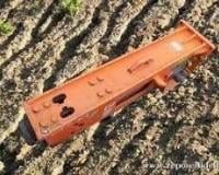
Ask for inspection of your NPK E 206 Enviro from experts
Mevas is an international operating inspection service for used heavy machinery. Construction machinery inspectors are available in more than 20 countries.
Use this service to minimise the risk when buying used equipment. An inspection by Mevas costs less than repairing a defective hydraulic cylinder.
Get spare parts for NPK E 206 Enviro easily from our partners
Do your lookup for high quality parts for NPK E 206 Enviro online!
With a few, easy steps, you will find generic and genuine parts and replacements in well-catalogued lists. Wether you are dealer or an owner, LECTURA can lead you to the right direction.
Check the best offers from our partners and order the Hydraulic Breakers spare parts easily today - worldwide.
In case you want to transport your machine, apply our services. Seek for the ideal transport quotes for Hydraulic Breakers built on transport dimensions and weights. Our partners offer large-scale services to meet your demands.


.png)